Now let us add one
more switch to our topology and arrange two devices for each of them. Let’s
observe how the switches are making entries in their CAM/MAC table for the
devices connected to them.
Here we go:

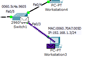
I just added Switch1
to our previous topology and connected both the switches (Switch0 & Switch1)
with their Fa0/5 ports. And the devices are connected to the ports as shown in
the pic.
Now let’s examine the
MAC tables of both the switches:
On Switch0: “show
mac-address-table”

On Switch1: “show
mac-address-table”

The MAC tables of
both switches have only one entry because none of the devices have communicated
from the past 300 seconds.
Now the question here
is whose mac is that, on both the switches?
It is the MAC address of the Fa0/5
interfaces of each of them. Since Switch0 is connected to the Fa0/5 port of
Switch1, Switch0 will have entry for Fa0/5 port of Switch1.
Similarly since Switch1 is connected
to the Fa0/5 port of Switch0, Switch1 will have entry for Fa0/5 port of
Switch0.
Let’s check it out practically:
We will see the MAC address of Fa0/5
port of both the switches.
On Switch0: “show
interfaces fastethernet 0/5”

The output is
truncated. From the output we can see that the hardware/MAC address of the
Fa0/5 port on Switch0 is: 0060.4731.5B05.
On Switch1: “show
interfaces fastethernet 0/5”

The output shows that
the hardware/MAC address of the Fa0/5 port on Switch1 is: 0060.5C4E.9605.
So it is clear now
that since Switch1 through its Fa0/5 port is connected to Switch0. Switch0 is
showing the MAC: 0060.54CE.9605 in its MAC table.
The same thing with Switch1: Since Switch0 through its Fa0/5 port is connected to Switch1. Switch1 is showing the MAC: 0060.4731.5B05 in its MAC table.
The same thing with Switch1: Since Switch0 through its Fa0/5 port is connected to Switch1. Switch1 is showing the MAC: 0060.4731.5B05 in its MAC table.
Here you may get a
doubt: Presently there is no communication between both the switches, then why
they are having the MAC entries of the ports joining them ?
The reason is, though the devices
are not communicating to each other from our perspective. There is a protocol
in Cisco called as “Cisco Discovery Protocol” which discovers the directly
connected cisco devices. The CDP protocol will send the CDP messages for every
180 second’s.
So here both the Switches are
exchanging CDP messages through their Fa0/5 ports, that is the reason for
having the MAC entries of the Fa0/5 ports of each other in their CAM tables
respectively. (We will discuss more on CDP later).
Now let’s go back to our topology to understand practically more
about the Switch functions:
For our convenience I labeled the ports joining both the switches with the MAC addresses.

Now let’s ping PC3 (192.168.1.3) on Switch1 from PC1 (192.168.1.1)
on Switch0:
Let us examine how both switches make
entries for both the devices (PC1 & PC3) in their MAC tables.

The ping was
successful. Now let’s check out the CAM table of both the Switches. By this
time we should be able to say which MAC will be mapped to which port on both
the switches. (Note down your answers on a paper and check them out)
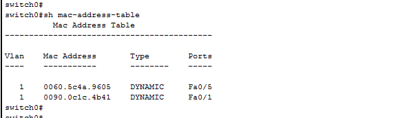
On Switch0: “show
mac-address-table”

Here two new entries
have found. One is: 0060.70A7.005D (PC3) & other is: 0090.0C1C.4B41 (PC1).
The MAC: 0090.0C1C.4B41 is
associated to Fa0/1 port because it is of the PC1 which is connected to Fa0/1
port of Switch0.
The MAC: 0060.70A7.005D is of the
PC3 and is associated/mapped to Fa0/5 port because PC3 is located on Switch1 and from
Switch0 the only way to Switch1 is through its Fa0/5 port, so Switch0
associated/mapped the MAC address of PC3 to its Fa0/5 port.
On Switch1: “show
mac-address-table”

Coming to Switch1,
here also there are two new entries. One is: 0060.70A7.005D (PC3) & other
is: 0090.0C1C.4B41 (PC1).
The MAC: 0060.70A7.005D is
associated to Fa0/3 port because it is of the PC3 which is connected to Fa0/3
port of Switch1.
The MAC: 0090.0C1C.4B41 is of the PC1
and is associated to Fa0/5 port because PC1 is located on Switch0 and from
Switch1 the only way to Switch0 is through its Fa0/5 port, so Switch1
associated/mapped the MAC address of PC3 to its Fa0/5 port.
Let’s dig more into the above explanation using frames
generated, step by step:
When I try to ping 192.168.1.3 (PC3)
from (PC1) 192.168.1.1:
1. The first frame generated will by by
PC1 towards Switch0 on its Fa0/1 port.
2. Now the switch0 will receive this frame on its Fa0/1 port and will
perform its learning function.
Here
is the PDU information from Switch0 for the first frame it received on its
Fa0/1 port.
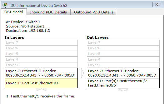
The above figure shows that a frame
has been received on Fa0/1 port from the device: 0090.0C1C.4B41 (PC1) and is destined for the device with MAC: 0060.70A7.005D (PC3).
Let’s see whether the switch has
performed its learning function or not.
On Switch0: “show mac-address-table”
From the above output we can confirm that the Swtich0 has performed its learning function. It mapped/associated the PC1 MAC: 0090.0C1C.4B41 to its Fa0/1 port.

4. Now the switch0 is going to flood the frame to its active ports: Fa0/2 & Fa0/1. (Remember that switch doesn’t bother about the device connected to it, it just reads the MAC address of the NIC interface of the device)

5. Now the flooded frame will be rejected by Wstation2 but it will be accepted by Switch1 because it is a switch & it will think that the destination device may be connected to me, so let me accept the frame.
(Actually switch accepts a frame after validating few things, we will discuss them as we go on). For now the Switch1 will accept the frame. (Don’t worry about the position of the frame in the pic)
 |
|
Wstation2 rejected the frame &
Switch1 accepted the frame.
|
6. Now again, what is the first function of the Switch1 ? It is nothing but it has to perform its learning function. So Switch1 will first compare whether or not the Source MAC address:0090.0C1C.4B41 is present in the CAM table.
Since it is not present, it will add it to its CAM table. Let check it.
On Switch1: “show mac-address-table”
 |
|
Switch1 has mapped the PC1’s MAC:
0090.0C1C.4B41 to Fa0/5 port.
|
7. Now the next function of the switch1 is forwarding. So first it checks whether the destination MAC is in it’s CAM table or not. Since the destination MAC is not present in it’s CAM table, now the switch1 will flood the frame to all of its active ports.
Here is the PDU information:


9. So PC3 has accepted the frame. Here is the PDU information on PC3 for the received frame.

The above information says that the
destination MAC address has matched the receiving interface MAC address.

11. Now Switch1 has receive4d this reply frame with above fields from PC3.

On Switch1: “show mac-address-table”

So from the output we confirm that Switch1 has learned the source mac from the frame and it has mapped/associated it to its Fa0/3 port.
13. Now the next function of the switch is to forward the frame to the destination MAC. The Switch1 will examine its CAM table and finds an entry for the destination MAC. So it is going to forward the frame to Fa0/5 port as per the CAM table.

14. Now
the frame has been received by the Switch0 on its Fa0/5 port. Here is the
PDU information.

The above figure shows that a frame
has been received on Fa0/5 port from the device: 0060.70A7.005D (PC3) and is
destined for the device with MAC: 0090.0C1C.4B41 (PC1).
Let’s see whether the switch has
performed its learning function or not.
On Switch0: “show mac-address-table”

From the above output
we can confirm that the Swtich0 has
performed its learning function.
It mapped/associated the PC3 MAC: 0060.70A7.005D to its Fa0/5 port.
15. Now the
next function of the switch0 is forwarding. So first it checks whether the
destination MAC is in it’s CAM table or not. Since the destination MAC is
present in it’s CAM table, now the switch0 will forward the frame to Fa0/1 port
as per the CAM table.

16. Finally
PC1 will receive this reply frame of PC3.

This is how the switch helps the
devices connected to it communicate each other.
In the next post we will discuss about the different type of frames a switch will receive and how it process them.
No comments:
Post a Comment